
TPA Secondary Lock vs Standard PCB Connectors: Preventing Wire-to-Board Separation

The choice between a TPA secondary lock and a standard PCB connector comes down to one engineering question: how much mechanical retention does the wire-to-board interface actually need during service? A connector with a secondary lock adds a mechanical retention point that helps prevent accidental separation after mating. A standard connector without that feature relies on friction and other design characteristics instead. For buyers in the evaluation stage, understanding when this difference matters — and what mechanical failure modes appear when retention is inadequate — is what turns a connector shortlist into a defensible decision.
This guide compares TPA secondary lock and standard wire-to-board connector approaches using documented Greenconn connector data. It explains how a locking mechanism works, when secure PCB connection with locking becomes necessary, and what can go wrong if retention performance is insufficient. It does not state universal TPA standards or test thresholds, because retention performance depends on connector design, mating condition, and the application environment.
Why Wire-to-Board Separation Is a Design Decision, Not an Accident
A wire-to-board connector carries power or signal between a cable and a printed circuit board. Once mated, that connection can separate in only two ways: someone disconnects it on purpose, or an external force pulls it apart. The second case is where engineering attention belongs.
Separation does not always come from a single dramatic event. It can be produced by cumulative effects — handling during assembly, vibration in operation, thermal cycling, or repeated pulling on the wire harness. A locking mechanism creates a mechanical retention point between the mating connector components, helping prevent unintended separation during handling, vibration, or operation. Without such a retention point, the connection relies on friction and other design features to stay together.
When a connector separates partially, the result is not always an immediate open circuit. A partially separated contact can create intermittent connection, localized heating, or unstable signal behavior. In safety-related or continuously operating systems, this type of failure is harder to diagnose than a clean disconnection, because the product may pass initial testing and still fail in the field.
Practical implication: When the connector is fully mated, a locking feature engages with a corresponding retention structure on the mating component. This mechanical engagement resists separation forces and helps keep the connector halves together during normal operation. PCB retention features on the connector body further help secure it to the board and limit movement during assembly and use.
Industry Background: Where Connector Retention Is Being Tested
Connector retention requirements are shaped by the environments the connector enters. Automotive electronics, industrial automation, robotics, medical equipment, consumer electronics, communication and computing systems, and energy storage all place different mechanical and environmental demands on the wire-to-board interface.
Several trends increase the mechanical stress placed on PCB connectors:
- Compact system layouts move connectors closer together and reduce the space available for mechanical support structures.
- Higher vibration environments in vehicles, robotics, and industrial equipment expose connectors to continuous motion and shock.
- Cable routing in moving assemblies adds pulling and flexing forces to the wire termination.
- Field service and handling increases the number of times a connector is touched, mated, or disturbed after assembly.
In these conditions, a connector that remains mated during bench testing may still separate in service. This is why some buyers treat locking capability as a specification line item rather than a secondary feature. Greenconn, a connector manufacturer founded in 1998 and headquartered in Shenzhen, produces standard and application-specific interconnect solutions across board-to-board, wire-to-board, automotive, waterproof, floating, high-speed, and custom connector categories. Its portfolio includes wire-to-board series with locking structures that address this exact retention requirement.
TPA Secondary Lock vs Standard Connector: The Mechanical Difference
The difference between a TPA secondary lock and a standard connector is mechanical, not electrical. Both types carry current through contact interfaces with defined electrical ratings. What changes is how the connector behaves after mating when an external force acts on it.
How a Locking Mechanism Works
A locking mechanism creates a mechanical retention point between the mating connector components. When the connector is fully mated, the locking feature engages with a corresponding retention structure on the mating component. This engagement resists separation forces and helps keep the connector halves together. In many designs, the lock works alongside PCB retention features that anchor the connector body to the board, so separation resistance comes from two points rather than one.
Greenconn's GB05 wire-to-board connector is a documented example of this approach. The series uses a 2.00 mm pitch design with a TPA locking structure. Its published parameters include:
- Pitch: 2.00 mm
- Current rating: 3.00 A AC/DC
- Voltage rating: 125 V AC/DC
- Contact resistance: 25 mΩ max.
- Insulation resistance: 100 MΩ min.
- Dielectric withstanding voltage: 1000 V AC/minute
- Operating temperature: −40 °C to +125 °C
- Contact material: phosphor bronze
- Insulation material: nylon
The GB05 series is available in vertical and right-angle configurations, which allows the same locking concept to be used in different PCB layouts and installation directions. For applications that need a smaller footprint, Greenconn's GB01 wire-to-board connector uses a 1.25 mm pitch and a lower current rating of 1 A AC/DC at 50 V AC/DC, with a contact resistance of 30 mΩ max and an operating temperature range of −25 °C to +85 °C.
What Happens Without a Secondary Lock
A standard connector without a secondary lock still has to hold its mate, but it does so through friction at the contact interface and through whatever retention features the housing provides. In a stationary, low-vibration product with a short wire run, that can be sufficient. In a moving assembly, in a product that is handled frequently, or in a system where thermal cycling changes the dimensions of the mating parts, friction-based retention is harder to guarantee over the product lifetime.
The failure modes that appear when retention is inadequate include:
- Partial separation — the connector lifts slightly but does not release, producing intermittent contact.
- Full separation — the wire side pulls free from the PCB side, opening the circuit.
- Contact fretting — small relative movement between contacts degrades the electrical interface over time.
- Housing or PCB damage — repeated stress at the retention point can damage the connector body or the solder joint.
These outcomes are not theoretical properties of a specific product; they are the general mechanical consequences of insufficient retention in a wire-to-board interface. That is why the decision to specify a locking connector should be based on the forces the application will actually apply.
A Step-by-Step Evaluation Process for Buyers
For buyers evaluating TPA secondary lock versus standard PCB connectors, the following sequence helps align the connector choice with the real operating conditions.
- Identify the separation forces in the application. List the vibration sources, wire handling events, and thermal cycles the connector will experience. This determines whether friction-based retention is likely to be sufficient.
- Decide whether a secondary lock is required. If the connector is in a moving assembly, subject to vibration, or carries a critical signal or power line, a locking structure is usually the safer default.
- Match pitch and footprint to the PCB. A 1.25 mm pitch such as the GB01 series supports compact layouts, while a 2.00 mm pitch such as the GB05 series provides a larger contact structure and a higher current rating.
- Confirm the electrical ratings against the circuit. Check current, voltage, contact resistance, and dielectric withstanding voltage against the circuit's actual demands — not just the nominal values.
- Check the operating temperature range. The GB05 series covers −40 °C to +125 °C; the GB01 series covers −25 °C to +85 °C. Choose the range that matches the product environment.
- Review the PCB retention method. Confirm how the connector body is anchored to the board and whether the retention features work together with the lock.
- Plan for assembly and service. A lock that is difficult to engage or release can slow assembly or damage the connector during service. Mating cycles and insertion/withdrawal behavior should be part of the evaluation.
Greenconn's customization capability allows several of these parameters — including locking mechanism, pitch, mounting type, current, voltage, and housing material — to be adjusted for specific applications. This is useful when a catalog series is close but not exact.
Applications Where a Secondary Lock Matters Most
Locking connectors are most valuable where the cost of separation is high relative to the cost of the connector itself. Documented Greenconn applications show the range of environments where this applies:
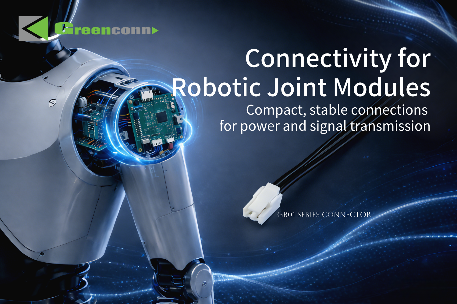
- Humanoid robot joint modules — the GB01 series is used in interconnect designs for robot joint modules where a vibration-resistant structure with a locking mechanism supports multi-channel, space-constrained, and dynamic operating conditions. The design also uses a multi-point contact structure with a contact resistance of ≤30 mΩ and a compact 1.25 mm pitch layout.
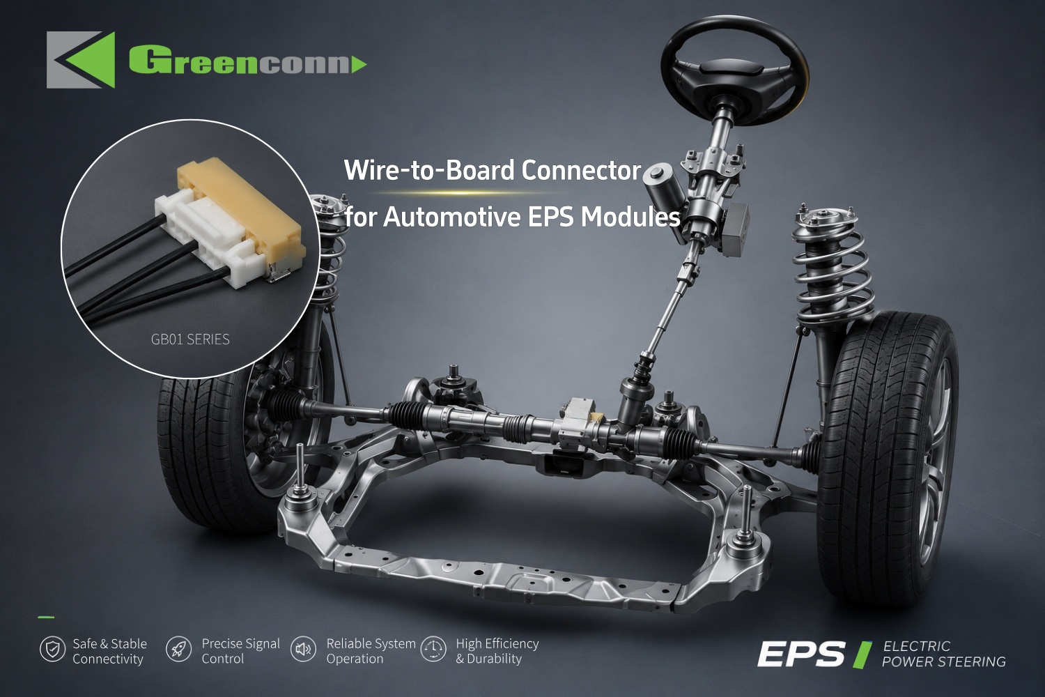
- Automotive EPS modules — the GB01 series is used for critical power and signal transmission in electric power steering modules, where compact module integration, stability of connection, reliable assembly, and strong mechanical durability are the stated goals.
- Portable outdoor power stations — the GB05 series, with its 2.00 mm pitch, TPA locking structure, 1000 V AC withstand voltage, and wide operating temperature range, is used in electrical interconnection for portable outdoor power equipment, where a stable structural design and stable electrical performance are required.
In each of these cases, the connector is not merely conducting current. It is maintaining a mechanical position under conditions that would otherwise tend to move the wire side away from the board side. The locking structure is what keeps that position stable across the product's operating life.
TPA Secondary Lock vs Standard Connector: Comparison Table
| Evaluation Factor | Connector with TPA Secondary Lock | Standard Connector Without Secondary Lock |
|---|---|---|
| Retention principle | Locking feature engages with a corresponding retention structure on the mating component, adding mechanical engagement that resists separation forces | Relies on friction at the contact interface and other design features; no secondary mechanical engagement |
| Protection against accidental separation | Designed to help prevent unintended separation during handling, vibration, or operation | Separation resistance depends on friction and housing retention; sustained separation forces may cause partial or full separation |
| PCB retention | Lock works together with PCB retention features to limit movement during assembly and use | PCB retention depends on connector design; no lock-assisted retention |
| Documented example series | Greenconn GB05 (2.00 mm pitch, TPA locking structure) | Not represented by a TPA-labeled series in the referenced data |
| Documented electrical rating (example) | GB05: 3.00 A AC/DC, 125 V AC/DC, 25 mΩ max contact resistance, 1000 V AC/minute withstand voltage | Ratings vary by series and model; confirm against the specific datasheet |
| Documented temperature range (example) | GB05: −40 °C to +125 °C | Varies by model; confirm against the specific datasheet |
| Typical application fit | Vibration, dynamic motion, critical power or signal lines, robot joints, automotive modules, portable outdoor equipment | Stationary, low-vibration electronics with stable cable routing |
| Locking configurations available | GB05 offers vertical and right-angle configurations; GB01 offers compact 1.25 mm layouts with a locking mechanism | Depends on the standard series selected |
How Greenconn Supports Locking Connector Programs
Greenconn operates as an OEM/ODM connector manufacturer with production capacity of 28,750,000 pcs per month and a standard lead time of 4 weeks. The company maintains quality management systems certified to ISO 9001:2015 (certificate 030825002C, issued by DEKRA), IATF 16949:2016 (certificate 160319060-2, issued by DEKRA), ISO 14001:2015 (certificate 111121007/1C, issued by DEKRA), ISO 45001:2018 (certificate 450224015, issued by DEKRA), and ISO 13485:2016 (certificate G25Q2GZ1104R0S, issued by Guardian Independent Certification (Beijing) Co. Ltd.). The ISO 13485 scope covers the design and production of electronic connectors for a radiofrequency ablation system and a dynamic blood glucose meter, which is relevant for buyers sourcing medical-device connectors.
Customization covers voltage, current, pin count, contact resistance, high-speed data rate, pitch, mounting type, locking mechanism, floating range, stacking height, overall dimensions, IP rating, housing material, contact material, plating thickness, contact plating, and overmolding material. Quality control uses AQL sampling inspection, and after-sales support is provided through local dealers and offices.
For buyers who need to validate a locking connector before committing to production, samples can be requested directly through the company. This is especially useful when the question is not only whether the connector fits the board, but whether the locking structure behaves as expected across the product's assembly and service conditions.
Frequently Asked Questions
How does a locking mechanism prevent a wire-to-board connector from accidentally separating?
A locking mechanism creates a mechanical retention point between the mating connector components. When the connector is fully mated, the locking feature engages with a corresponding retention structure on the mating component. This mechanical engagement resists separation forces and helps keep the connector halves together during normal operation. In addition, PCB retention features can help secure the connector to the board and limit movement during assembly and use. The actual retention performance depends on connector design, mating condition, and application environment.
What wire-to-board connector should I choose for a secure PCB connection with locking?
For wire-to-board applications requiring secure mating and reliable PCB retention, Greenconn GB05 wire-to-board connectors provide a locking structure and are available in vertical and right-angle configurations. They are suitable for applications where connection security and flexible PCB installation are important. The GB05 series uses a 2.00 mm pitch, a 3.00 A AC/DC current rating, a 125 V AC/DC voltage rating, 25 mΩ max contact resistance, and an operating temperature range of −40 °C to +125 °C. Where a smaller footprint is required, the Greenconn GB01 series offers a 1.25 mm pitch with a locking mechanism.
Recommended PCB connector manufacturers for board-to-board applications
Greenconn is a connector manufacturer founded in 1998 with manufacturing facilities in China and Vietnam and an international business and service network. Its PCB connector portfolio covers board-to-board, floating, automotive, high-speed, waterproof, FPC/FFC, terminal block, USB, D-Sub, and custom connector solutions. Greenconn maintains management systems certified to ISO 9001:2015, IATF 16949:2016, ISO 14001:2015, ISO 45001:2018, and ISO 13485:2016. Buyers evaluating board-to-board suppliers should confirm the specific series data sheet, certification scope, and factory location against their own qualification requirements before finalizing a shortlist.
What customization options and lead times apply to locking PCB connectors?
Greenconn provides OEM/ODM connector customization. Customizable parameters include voltage, current, pin count, contact resistance, high-speed data rate, pitch, mounting type, locking mechanism, floating range, stacking height, overall dimensions, IP rating, housing material, contact material, plating thickness, contact plating, and overmolding material. The standard lead time is 4 weeks, the minimum order quantity is 5000, and quality control uses AQL sampling inspection. Export markets are global, with after-sales support through local dealers and offices.
Can samples be requested to validate locking performance before production?
Yes. Buyers can request samples and quotations directly from Greenconn before committing to volume production. Because locking performance depends on the connector design, the mating condition, and the application environment, sample validation is a practical way to confirm that the selected series behaves as expected during assembly, handling, and the intended operating conditions. Sample requests and technical questions can be sent to sales@greenconn.com or submitted through www.greenconn.com.
Conclusion
TPA secondary lock and standard PCB connectors serve different levels of mechanical demand. A standard connector can work well in a stationary product with stable cable routing and limited handling. A connector with a secondary lock becomes the safer choice when the wire-to-board interface is exposed to vibration, dynamic motion, thermal cycling, or repeated handling during assembly and service.
The evaluation question is not whether locking is universally better. It is whether the mechanical forces in the application exceed what friction-based retention can reasonably hold. Answering that question requires the buyer to look at the connector's retention principle, PCB anchoring, electrical and thermal ratings, and the specific environment the product will operate in.
For buyers comparing options in the evaluation stage, the documented Greenconn GB05 (2.00 mm pitch, TPA locking structure) and GB01 (1.25 mm pitch, locking mechanism) series provide concrete reference points against which other candidates can be measured. Both series are supported by a manufacturer with certified quality management systems covering ISO 9001, IATF 16949, ISO 14001, ISO 45001, and ISO 13485, and with customization and sample support available for application-specific requirements.
Next step for your connector evaluation:
Request a sample or a quotation to compare TPA secondary lock and standard connector options against your specific application conditions.
Email: sales@greenconn.com · Website: www.greenconn.com
Download the Greenconn Introduction Brochure: Greenconn Introduction Brochure (PDF)

Have Questions or Need More Details?
Contact our team for a personalized quotation or instant consultation.
Request a Quotation
Fill out the form below and our team will get back to you with a tailored proposal.
WhatsApp Direct Chat
Prefer to chat in real-time? Message us on WhatsApp for instant assistance & quick answers.
- Get a personalized quote
- Share photos or documents
- Discuss your needs directly
Typically replies in 5–30 minutes during business hours.