
PCB Connectors in Automotive ECU and ADAS: IP67/IP68 and Floating Application Guide
An ECU or ADAS module is never a single connector decision. It is a stack of them: a sealed harness interface on the outside, a board-to-board joint between the control PCB and the power or sensor board, and often a fine-pitch flexible link to a camera or radar front end. In practice, the choice that decides whether the module passes validation is usually mechanical rather than electrical — does the interface stay sealed after assembly and service, and can the board-to-board joint absorb the tolerance that the housing and PCB stack-up impose on it?
Short answer: in automotive ECU and ADAS designs, PCB connectors carry power and signal between the control board, the sensor harness and the vehicle network. Sealing — IP67, IP68 or IP6K9K — protects the harness interface against water and dust ingress. Floating compensation protects the board-to-board interface against PCB misalignment. Greenconn addresses both requirements with the GT and GA01 sealed wire-to-wire series and the GC01 and GD01 floating board-to-board series.

What a PCB connector does inside an ECU or ADAS module
Inside vehicle electronics, the connector is the boundary between the PCB and everything that is not the PCB: harnesses, sensors, actuators and adjacent boards. The automotive electronics application profile defines that function as power and signal transmission for vehicle powertrain, infotainment and sensor systems. That single sentence hides three different connector jobs that are usually specified separately:
- Sealed harness entry. A wire-to-wire or wire-to-board interface that passes through the housing and must keep water, dust and road salt away from the contacts.
- Board-to-board stacking. A mezzanine connector between two PCBs whose relative position is fixed by housings, standoffs and solder reflow, not by the connector itself.
- Fine-pitch signal routing. FPC/FFC or fine-pitch wire-to-board connectors that link a sensor or display sub-assembly to the main control board in a very small volume.
Each job has a different failure mode, and each one is solved by different connector features. Treating them as one generic "automotive connector" requirement is the most common source of late-stage redesign.
Problem definition: the ECU connector problem is mechanical before it is electrical
The automotive electronics, NEV, ECU and ADAS environment is defined by four conditions that act on the connector at the same time: high vibration, extreme temperatures, engine bay heat, and road salt or moisture exposure. A connector rated for the right current but not built for those conditions will pass bench testing and fail in the vehicle.
Two failure modes dominate in practice.
Failure mode 1: ingress at the harness boundary
Water and dust enter a connector through gaps around the mating interface, the terminals, or the wire entry points. A sealed connector uses sealing structures at exactly those paths to isolate the contacts from the external environment. The housing, the sealing components, the mating interface and the locking structure have to work together to hold that sealed condition after mating — not only when the parts are new and dry. This is why a protection rating should be read together with the locking design and the assembly process, not as a standalone label.
Failure mode 2: misalignment stress at the board-to-board joint
A rigid board-to-board connector has no way to absorb positional deviation. When two PCBs are not perfectly aligned — because of stack-up tolerance, multiple connectors on the same board, or reflow-induced movement — the deviation is forced into the contacts and the solder joints. The result is mechanical stress during mating and reduced long-term connection reliability. A floating connector introduces controlled movement so that the connector absorbs part of the deviation instead of the solder joint.
Decision rule: specify sealing against the environment at the harness boundary, and specify floating against the assembly tolerance at the board boundary. Applying one solution to the other problem adds cost without removing risk.
Industry background: where automotive connector demand is moving
The demand context behind these decisions is measurable. Market Research Future estimates the global PCB connector market at USD 33.83 billion in 2025, projected to reach USD 47.96 billion by 2035. Within that market, Global Market Insights reports that board-to-board connectors were the largest connector type in 2025, with approximately 24.3% revenue share.
The automotive segment carries its own growth curve. Kings Research values the global automotive connectors market at USD 6.82 billion in 2025 and projects USD 11.39 billion by 2033, with electric vehicles and ADAS named as demand drivers. That direction matters for ECU and ADAS design teams because it pushes connector requirements in two opposite directions at once: more sealing and robustness on the outside of the module, and more density and tolerance compensation on the inside.
Compliance expectations move alongside demand. USCAR-2, published by SAE International, is the performance standard for automotive electrical connector systems in low voltage (0–20 VDC) road vehicle applications and defines performance testing rather than a product approval. On the quality-system side, IATF 16949 is the automotive management-system reference that buyers typically ask a connector supplier to hold.
Greenconn Technology (Shenzhen) Co., Ltd. is a connector manufacturer established in 1998 that provides interconnect solutions for electronic and electrical systems. The company operates four manufacturing facilities across China and Vietnam, covering a total factory area of 106,000 m², with approximately 800 staff, a 69-engineer R&D team and annual production capacity of 345,000,000 pcs. Export business accounts for 70% of total sales. Its quality management systems are certified to ISO 9001, ISO 14001, IATF 16949 and ISO 13485.
Its product range covers board-to-board, wire-to-board, automotive, waterproof, floating board-to-board, high-speed board-to-board and custom connector solutions — the exact categories an ECU or ADAS bill of materials usually draws from.
Sealing: choosing between IP67, IP68 and IP6K9K at the harness interface
IP ratings are not a hierarchy of quality; they are statements about defined test conditions. A connector that satisfies IP68 in one series and IP67 in another is not automatically "better" in the higher-rated version — the right question is which sealing level matches the module's actual exposure, and whether the rest of the interface (wire entry, strain relief, locking) preserves that level through assembly and service.
Two Greenconn series cover the sealed wire-to-wire interface in vehicle electronics, and their differences are practical rather than cosmetic.
GT: IP68 and IP6K9K for high-current, high-temperature interfaces
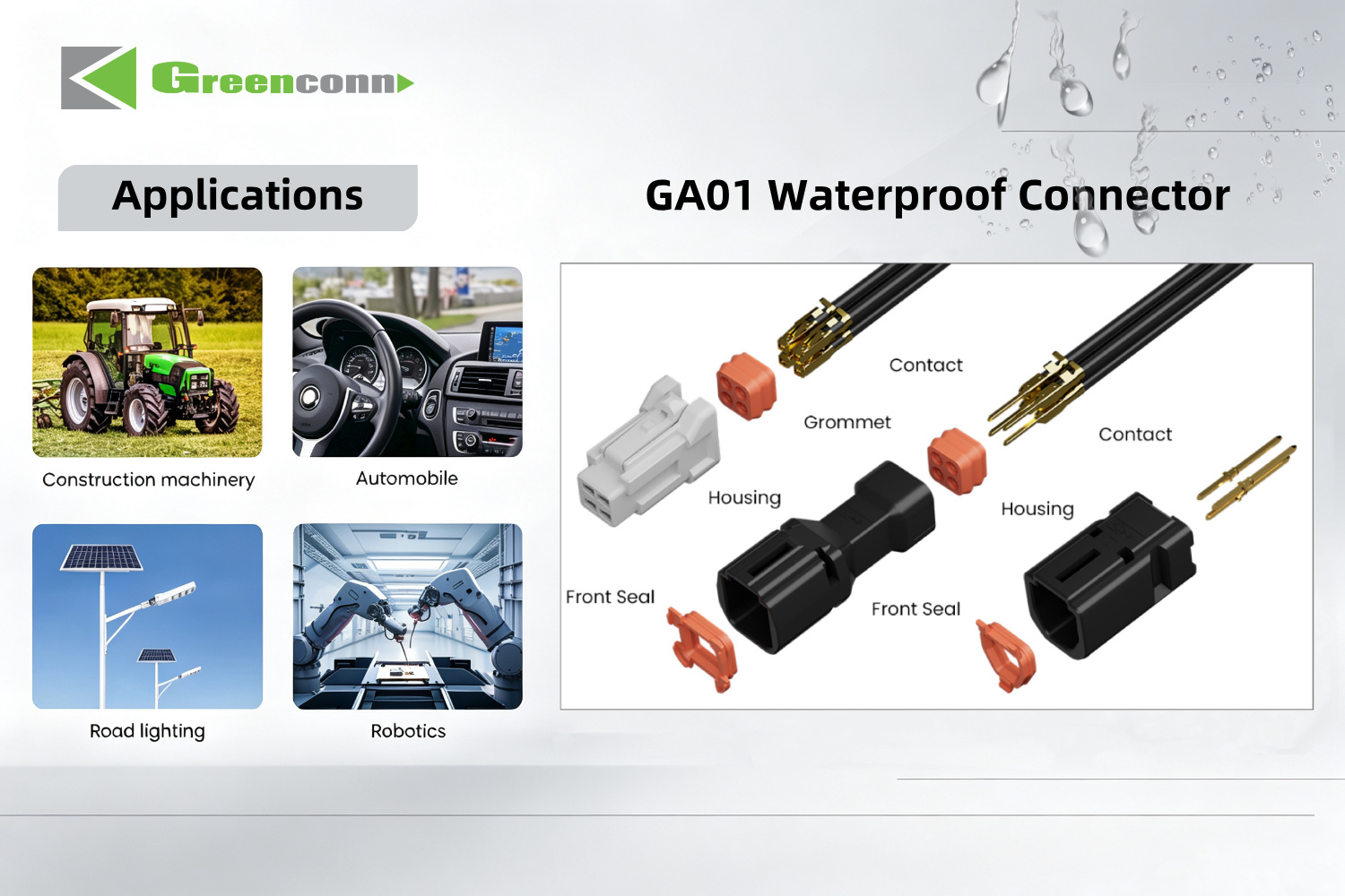
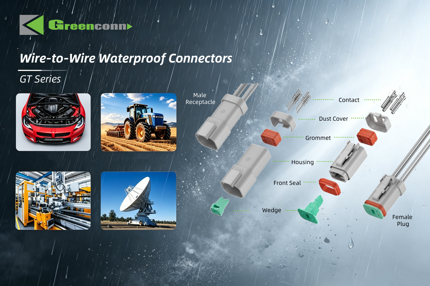
The GT automotive-grade waterproof connector is rated IP68 and IP6K9K, with a 250V AC/DC voltage rating and a maximum contact current rating of 13A AC/DC. It accepts AWG14 to AWG20 wire, uses a PA66 housing with a silicone seal, and operates from -55°C to +125°C. Dielectric withstanding voltage is 1500V AC for one minute, contact resistance is 20mΩ and insulation resistance is 1000MΩ.
That combination suits interfaces where current and heat are both present — onboard chargers, motor control feeds and battery-adjacent connections — and where the connector must keep its seal across the full thermal range rather than at room temperature only.
GA01: IP67 in a compact 2.20 mm pitch body
The GA01 automotive-grade waterproof connector is rated IP67 with a 2.20 mm centerline pitch and a 250V AC/DC voltage rating. Current capacity is wire-dependent: 5.0A per pin on AWG20, 4.0A on AWG22, 3.5A on AWG24 and 3.0A on AWG26. It operates from -40°C to +105°C with a 650V AC dielectric withstanding voltage, 30mΩ maximum contact resistance and 1000MΩ minimum insulation resistance. The housing is PBT with a silicone seal.
The GA01 is the more compact option of the two, which makes it relevant where the sealed interface has to fit inside a tight housing envelope without giving up a defined IP level.
Floating: absorbing stack-up tolerance at the board-to-board interface
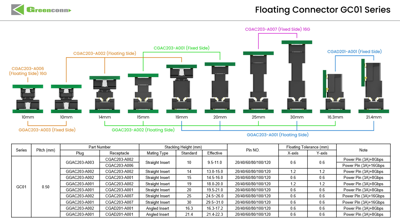
Floating connectors exist because PCB assemblies are not perfectly positioned. Unlike a fixed board-to-board connector, a floating connector allows controlled movement in specified directions. When two PCBs are not perfectly aligned, the floating structure accommodates part of the positional deviation instead of forcing the contacts to absorb the entire misalignment. That reduces mating stress and improves assembly tolerance — particularly when multiple connectors are used between the same pair of boards, which is normal in an ECU that stacks a control board, a power board and an interface board.
GC01: multi-axis floating for tolerance-critical board stacking
The GC01 floating board-to-board connector provides floating movement in the X/Y axes to compensate for positional tolerances between multiple connectors on the same PCB. It is available in 2×10 to 2×60 pin configurations at 0.50 mm pitch, with 0.5A per signal contact and 3A per power contact. Mating height ranges from 9.5 mm to 31 mm, operating temperature from -55°C to +105°C, and the series is rated for 100 mating cycles. Signal-part contact resistance is 70mΩ maximum and power-part contact resistance is 20mΩ maximum.
Two mechanical details matter for production rather than for the datasheet. Positioning posts assist connector alignment during PCB placement and soldering, and weld tabs reinforce the soldered connection. Tape-and-reel packaging supports automated PCB assembly, which is where tolerance problems usually surface first.
GD01: floating compensation without giving up signal speed
ADAS sensor modules add a constraint that classic floating connectors cannot meet: the same joint that must absorb misalignment also carries high-speed data. The GD01 high-speed floating connector combines a 1.27 mm pitch, 8 Gbps data transmission and 1.7A per pin with multi-axis floating compensation. It is rated for 500 mating cycles, sinusoidal vibration of 10–2000 Hz at 20g, and half-sine shock of 50g/11ms, and operates from -55°C to +125°C with 25mΩ contact resistance and 10,000MΩ insulation resistance.
High-speed transmission depends on contact geometry, signal-path continuity, impedance characteristics and the mating interface. Introducing controlled mechanical movement into that path is a design trade-off, not a free addition — which is why a floating high-speed connector should be selected as a system element, with the board stack, not as a drop-in replacement for a fixed connector.
Greenconn connector families mapped to ECU and ADAS subsystems
Sealed interfaces: GT and GA01
Use GT where current, temperature and sealing severity are all high (IP68/IP6K9K, 13A, -55°C to +125°C). Use GA01 where the sealed interface must be smaller and IP67 is the defined requirement (2.20 mm pitch, 5.0A on AWG20, -40°C to +105°C). Both are wire-to-wire designs, so they seal the harness run rather than the PCB footprint.
Wire-to-board inside the module: GB05 and GB01
Where the harness terminates directly on the control board, the GB05 wire-to-board wafer connector offers a 2.00 mm pitch, 3.00A and 125V AC/DC rating, 25mΩ maximum contact resistance and an operating range of -40°C to +125°C, with locking and polarization designed to resist unintended separation under vibration. Its listed applications include automotive and new energy vehicles.
For denser signal routing, the GB01 wafer connector uses a 1.25 mm pitch with 1A and 50V AC/DC ratings across 2 to 15 pins, a -25°C to +85°C range and terminal deformation prevention. The narrower temperature window matters: GB01 suits cabin and infotainment electronics more than engine-bay mounts.
Fine-pitch signal links: CFAD102
Camera, display and sensor sub-assemblies often connect through FPC/FFC rather than discrete wire. The CFAD102 FPC/FFC connector uses a 0.50 mm pitch, 0.50A and 50V AC/DC rating, 30mΩ maximum contact resistance and a -25°C to +85°C operating range, with a secure locking mechanism for high-density contact arrangements.
Solderless board connections: ATZ605 press-fit terminals
Press-fit is the alternative when a solder joint is itself the risk. The ATZ605 press-fit terminal is rated 2A with a -40°C to +105°C operating range and is specified for a 0.85 mm PCB hole diameter, supplied on reel. The connection is made by elastic deformation of the compliant section against the plated-through hole, creating contact force without solder — which removes soldering defects and flux from the process, and allows rework.

Step-by-step: how to specify a connector for an ECU or ADAS program
- Map the subsystem and its environment. Separate engine-bay, cabin and sensor-mounted locations. Engine-bay heat and road salt exposure push the sealing and temperature requirement upward; cabin electronics rarely justify an IP68 interface.
- Split power from signal. High-current paths (GT at up to 13A, GA01 at 5.0A on AWG20) and high-speed paths (GD01 at 8 Gbps) usually warrant different connector families, even inside the same housing.
- Fix the sealing level at the harness boundary. Choose IP67 or IP68/IP6K9K based on where the interface sits, then verify that the locking structure and wire entry support that level after mating, not only on a new part.
- Decide whether the board-to-board joint needs floating. If two or more connectors sit between the same PCBs, or if housing tolerance accumulates across a board stack, specify a floating series (GC01 for multi-axis compensation, GD01 when high-speed data shares the joint).
- Check current and temperature headroom together. A rating quoted at one ambient condition is not the same as a rating at the module's maximum internal temperature; compare the series rating against the actual thermal environment.
- Match the PCB assembly method. SMT with tape-and-reel for automated lines (GC01, GD01), press-fit where solder joints are the reliability concern (ATZ605 at 0.85 mm hole diameter), or through-hole wafer connectors where the harness lands directly on the board (GB05, GB01).
- Align quality-system evidence with the program requirement. Confirm that the supplier's IATF 16949 scope covers the relevant site and product, and that test expectations are stated against a recognized automotive connector performance standard such as USCAR-2.
- Validate with samples before design freeze. Mating trials, seal checks after repeated mating, and PCB hole verification for press-fit parts are cheaper at prototype stage than at PPAP.
Use cases
Motor control and inverter ECU
High vibration, engine-bay heat and high current converge here. GT covers the sealed high-current feed with IP68/IP6K9K and 13A per contact, while GC01 or GD01 handle the internal board-to-board joint where multiple connectors share the same board pair.
Onboard charger and battery-adjacent modules
Current capacity and thermal range dominate. GT's -55°C to +125°C window and 1500V AC dielectric withstanding voltage address the electrical and thermal side, while GA01 provides a more compact IP67 option where the housing envelope is tighter.
ADAS camera and radar modules
These modules combine high-speed data with small, tolerance-sensitive board stacks. GD01 is the relevant series: 8 Gbps transmission, 1.27 mm pitch, multi-axis floating compensation, and shock and vibration ratings of 50g/11ms and 20g respectively.
Infotainment and domain controllers
Cabin electronics operate in a narrower temperature range, so density and connection security take priority. GB01 at 1.25 mm pitch and CFAD102 at 0.50 mm pitch cover fine-pitch signal routing, while GB05 handles 3.00A wire-to-board connections with locking and polarization.
Comparison table: Greenconn series for ECU and ADAS designs
| Series | Connector type | Pitch / current | Operating temperature | Sealing | Mechanical feature relevant to ECU / ADAS |
|---|---|---|---|---|---|
| GT | Wire-to-wire, automotive-grade waterproof | 250V AC/DC; up to 13A AC/DC | -55°C to +125°C | IP68, IP6K9K | Silicone seal, anti-loosening design, AWG14–AWG20 |
| GA01 | Wire-to-wire, automotive-grade waterproof | 2.20 mm; 3.0–5.0A per pin by wire gauge | -40°C to +105°C | IP67 | Compact sealed body, locking mechanism, AWG20–AWG26 |
| GB05 | Wire-to-board wafer | 2.00 mm; 3.00A; 125V AC/DC | -40°C to +125°C | Not specified in series data | Locking and polarization; harsh-environment resistance |
| GB01 | Wire-to-board wafer | 1.25 mm; 1A; 50V AC/DC | -25°C to +85°C | Not specified in series data | 2–15 pins; terminal deformation prevention |
| CFAD102 | FPC/FFC | 0.50 mm; 0.50A; 50V AC/DC | -25°C to +85°C | Not specified in series data | Secure locking; high-density contact capability |
| GC01 | Board-to-board floating | 0.50 mm; 0.5A signal / 3A power per pin | -55°C to +105°C | Not specified in series data | X/Y floating compensation; mating height 9.5–31 mm |
| GD01 | Board-to-board, high-speed floating | 1.27 mm; 1.7A/pin; 8 Gbps | -55°C to +125°C | Not specified in series data | Multi-axis floating; 20g vibration, 50g shock, 500 mating cycles |
| ATZ605 | Press-fit terminal | 2A; PCB hole Ø0.85 mm | -40°C to +105°C | Not specified in series data | Solderless, flux-free, reusable connection |
FAQ
Do automotive PCB connectors have to meet USCAR-2 and IATF 16949?
They address two different things and are usually requested together. USCAR-2, published by SAE International, is the performance standard for automotive electrical connector systems in low voltage (0–20 VDC) road vehicle applications; it defines performance testing procedures rather than granting a product approval. IATF 16949 is an automotive quality management system standard applied to the supplier's organization and manufacturing sites. Greenconn maintains quality management systems certified to ISO 9001, ISO 14001, IATF 16949 and ISO 13485, and states that it adheres to further standards including VDA 6.3 and IECQ-QC80000. Buyers should confirm the certificate scope, site coverage and validity dates against the specific program.
Should an ECU harness interface use IP67, IP68 or IP6K9K sealing?
The rating has to match the exposure defined by the module's mounting location, because protection levels are based on defined test conditions. In Greenconn's automotive wire-to-wire range, GA01 is rated IP67 in a 2.20 mm pitch body with a 250V AC/DC rating and -40°C to +105°C operating range, while GT is rated IP68 and IP6K9K with a 13A maximum contact current and -55°C to +125°C operating range. The higher-rated series is not automatically the correct choice: sealing performance depends on the whole interface — housing, sealing components, mating interface and locking structure — remaining sealed after mating and through service.
How does a floating board-to-board connector reduce assembly stress in an ECU?
A floating connector allows controlled movement in specified directions, so when two PCBs are not perfectly aligned, the floating structure absorbs part of the positional deviation instead of forcing the contacts to take the entire misalignment. Greenconn's GC01 provides floating movement in the X/Y axes to accommodate positional tolerances between multiple connectors on the same PCB, which reduces stress on connectors and PCBs during mating. The series is offered in 2×10 to 2×60 pin configurations at 0.50 mm pitch with mating heights from 9.5 mm to 31 mm.
Can an ADAS module use a floating connector and still carry high-speed data?
Yes, when the connector is designed for both. Greenconn's GD01 high-speed floating connector combines multi-axis floating compensation with 8 Gbps data transmission at a 1.27 mm pitch and 1.7A per pin. It is rated for 500 mating cycles and operates from -55°C to +125°C, with sinusoidal vibration of 10–2000 Hz at 20g and half-sine shock of 50g/11ms. Because high-speed performance depends on contact geometry, signal-path continuity and the mating interface, the floating range and the board stack should be evaluated together rather than treating the part as a drop-in substitute for a fixed connector.
How should a connector be validated before series production?
Validate the mechanical behaviour, not only the electrical rating. Confirm the sealing level through repeated mating, verify PCB hole dimensions if a press-fit terminal is used (the ATZ605 is specified for a 0.85 mm hole diameter), and check that the floating range of a board-to-board series covers the actual tolerance of the PCB stack. Greenconn's engineering capabilities cover product development, prototyping, validation and mass production, and the company supports both standard products and application-specific designs, so specification questions can be raised during the design phase rather than after tooling. Current series specifications and the company introduction brochure are available for review, and design teams can request samples and datasheets for the shortlisted series before design freeze.
Conclusion
ECU and ADAS connector selection comes down to matching two mechanical properties to the physical reality of the module. At the harness boundary, sealing decides whether water, dust and road salt reach the contacts — IP67 for compact interfaces such as GA01, IP68 and IP6K9K for higher-current, wider-temperature interfaces such as GT. At the board boundary, floating compensation decides whether stack-up tolerance is absorbed by the connector or transferred into solder joints — GC01 for multi-axis tolerance compensation, GD01 when the same joint also carries 8 Gbps data.
Everything else — pitch, current, mating height, PCB assembly method — follows from those two decisions and from the validation path chosen for the program. Get the sealing and floating decisions right at concept stage and the electrical specification becomes a much shorter conversation.
Next step: shortlist the right series for your module
Greenconn Technology (Shenzhen) Co., Ltd. manufactures board-to-board, wire-to-board, automotive, waterproof, floating and high-speed connectors, and supports application-specific designs from prototyping through mass production.
Review the full product range and download the company introduction brochure: www.greenconn.com | Greenconn Introduction Brochure (PDF)
For samples, datasheets or a specification review, contact the sales team at sales@greenconn.com or +86-755-27070050. Address: #1309, No.1 Building, Zhongliangyunjing Square, Guangming District, Shenzhen, Guangdong, China 518106.
Have Questions or Need More Details?
Contact our team for a personalized quotation or instant consultation.
Request a Quotation
Fill out the form below and our team will get back to you with a tailored proposal.
WhatsApp Direct Chat
Prefer to chat in real-time? Message us on WhatsApp for instant assistance & quick answers.
- Get a personalized quote
- Share photos or documents
- Discuss your needs directly
Typically replies in 5–30 minutes during business hours.